Pins
-
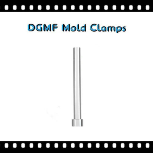
DGMF Straight Ejector Pins
Read more -
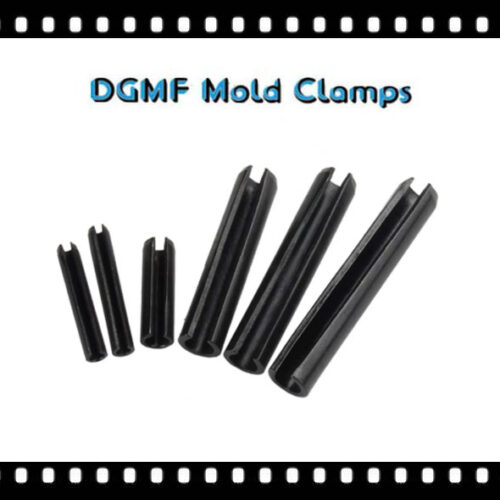
DGMF Slotted Spring Pins GB879
Read more -
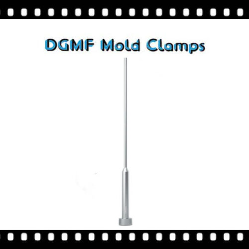
DGMF Shoulder Ejector Pins
Read more -
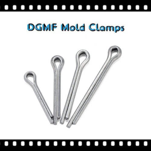
DGMF Lock Cotter Pins GB891
Read more -
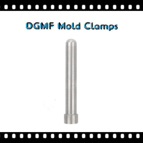
DGMF High-precision Angle Pins
Read more -
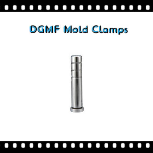
DGMF Guide Pins For Injection Molding
Read more -
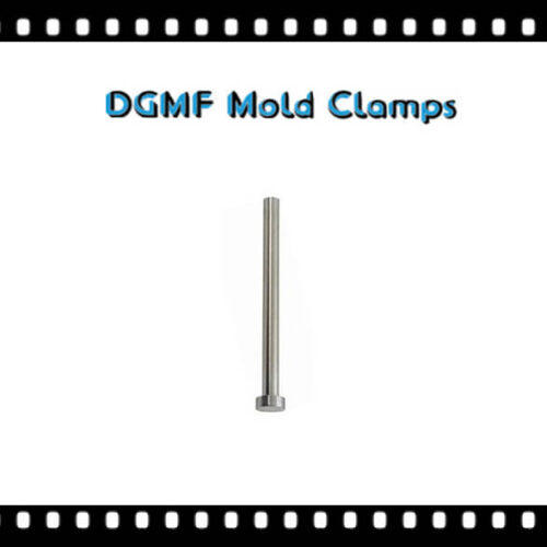
DGMF Ejector Sleeve Pins
Read more -
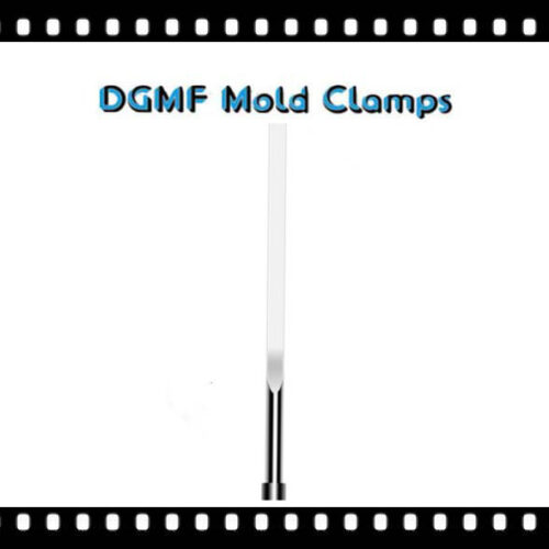
DGMF Ejector Blades
Read more -
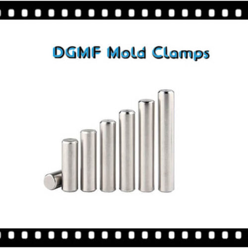
DGMF Dowel Pins Tubular Dowels GB119
Read more -
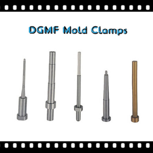
DGMF Core Pins for Molding
Read more -
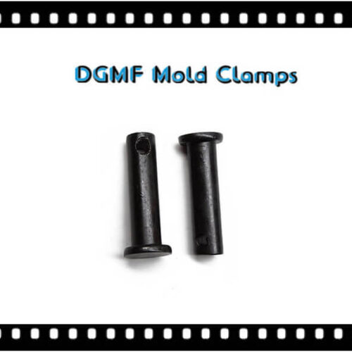
DGMF Clevis Pins GB882
Read more
Pins Supplier
DGMF Mold Clamps Co., Ltd is the pins supplier and mould clamps manufacturer in China.
What does the pin include?
The pins in the mold components series include ejector pins, ejector sleeve pins, guide pins, core pins, dowel pins, etc.
Ejector pin
An ejector pin is a kind of spare parts used in molds and plastic mold parts, used in plastic molds. An ejector pin can also be called an ejection pin, etc. Sometimes the top of the lathe is also called the Ejector pin.
Use of Ejector pin
1. In plastic molds, separating the product from the mold is also the most commonly used;
2. Carbide ejector pin, such as tungsten steel ejector pin, can be used to pass longer and finer holes;
3. The ejector pin is also called the ejection top. It is a conical metal round rod with a head that is assembled on a lathe or a grinder to support the workpiece and rotate the workpiece around it, but it is completely different from the ejector pin of the plastic mold components;
4. A plastic mold ejector pin can also be used inside the mold, it can play a stabilizing role and is called an inserted needle. The types of plastic mold ejector pins include straight ejector pins, shoulder pins, standard ejector pins, non-standard ejector pins, etc.
Plastic mold ejector pin materials include SKH51, SKD61, SKD11, 65Mn, etc. SKH51 thimble has better toughness than SKD61, and the SKD61 ejector pin can withstand a high temperature of 1600℃, SKD61 ejector pin surface nitriding treatment can improve the wear resistance of the thimble.
65Mn ejector pin is of poor quality, and the quality is brittle and easy to break. Most plastic molds are no longer assembled and use a 65Mn ejector pin.
The role of ejector pin
The ejector pin is a commonly used object in injection molds. In the process of molding and injection molding of the mold, the demolding of the product is usually achieved by three ejector pins, an ejector pins, a push, and a tube. So what is the ejector pin and what is the specific function?
There are two types of ejector pins, straight ejector pins, and shoulder ejector pins. The specific requirements must be determined by the structural position of the product.
During the injection molding process of the mold, when the mold cavity is filled with glue to start demolding, the ejector pin is ejected to the preset position by the mold push plate at the back of the mold, and the mold ejector pin pushes the product out to realize the separation of the product from the mold. Such a process is the function of the ejector pin on the mold.
Principle 1 of ejector pin selection
(1) The arrangement of the thimble should make the ejection force as balanced as possible. The demolding force required for complex structures is relatively large, and the number of ejectors should be increased accordingly.
(2) The ejector pin should be set in ineffective parts, such as bone position, column position, step, metal insert, local thick glue, and other complex structures. The ejector pin on both sides of the bone and bushing should be arranged symmetrically.
The distance between the ejector pin and the bone and the side of the column is generally D=1.5mm. In addition, try to ensure that the centerline of the thimble on both sides of the column passes through the center of the column.
(3) Avoid stepping over steps or arranging thimble on the inclined surface. The top surface of the ejector pin should be as smooth as possible, and the ejector pin should be arranged in the structural part of the rubber with better force.
(4) A shoulder ejector pin should be used when the glue is deeper (depth ≥20mm) or when it is difficult to arrange the straight ejector pin. When a shoulder ejector pin is needed, try to use the insert form at the shoulder ejector pin to facilitate processing.
(5) Avoid sharp steel and thin steel, especially the top surface of the ejector pin should not touch the front die surface.
(6) The arrangement of the ejector pin should consider the distance between the ejector pin and the waterway to avoid affecting the processing and water leakage of the waterway.
(7) Considering the exhaust function of the ejector pin, to exhaust during ejection, the ejector pin should be arranged in the part that is easy to form a vacuum.
For example, in the larger plane of the cavity, although the packing force of the rubber part is small, it is easy to form a vacuum, increasing the demolding force.
(8) For plastic molded parts with appearance requirements, the ejector pins cannot be placed on the appearance surface, and other ejection methods should be used.
(9) For transparent plastic molded parts, the ejector pin cannot be placed in the part that needs to be transparent.
The second principle of ejector pin selection
(1) Choose an ejector pin with a larger diameter. That is when there is enough ejection position, an ejector pin with a larger diameter and size priority should be used.
(2) The size of the ejector pin should be as few as possible. When choosing an ejector pin, the size of the ejector pin should be adjusted to minimize the size specifications, and at the same time try to choose the preferred size series.
(3) The selected ejector pin should meet the requirements of ejection strength. When ejecting, the ejector pin must withstand greater pressure.
In order to avoid bending and deformation of the small ejector pin, when the diameter of the ejector pin is less than 2.5mm, a supporting ejector pin should be used.
Ejector sleeve
The ejector sleeves and ejector pins are called the ejector pin and sleeve assembly, which is one of the plastic mold components.
The ejector sleeve is also called an ejector sleeve pin, or hollow ejector pin.
Classification
The ejector sleeve is divided into a straight ejector sleeve, a stepped ejector sleeve, etc.
Definition
The ejector sleeve is around the through-hole or blind hole on the product, and the glue position must be provided with a metal fitting of an ejector device used for ejection.
Composition
It consists of a cylinder and a cylinder needle. The cylinder is installed on the ejector plate, and the cylinder needle is installed on the bottom plate. After the mold is opened, the cylinder is ejected from the rubber position wrapped on the cylinder needle.
Related appliances
The sleeve, hole, or shaft acts on the wear or out-of-tolerance processing, the original position is stretched and moved, and a set is inserted to restore the original size.
The fixture of the ejector sleeve. Put some parts in the sleeve to facilitate positioning and clamping. This metal sleeve is called the ejector sleeve.
Ejector pin vs. ejector sleeve
The ejector pin and the ejector sleeve are two different mold components, but they can be used in plastic molds with each other.
Then, how to distinguish the ejector pin and the ejector sleeve?
1. Distinguish the shape of the ejector pin and ejector sleeve
The ejector sleeve is hollow, the ejector pin is solid, long, and has a sharp point, and the ejector pin is harder than the ejector sleeve.
2. The role of ejector pin and sleeve
The ejector pin and sleeve are composed of two parts, the ejector sleeve, and the inner needle ejector pin. The ejector sleeve is put on the inner ejector pin and can move up and down. The ejector pin is fixed on the bottom plate of the mold, and the main ejector sleeve is installed on the ejector plate.
When ejected, the main ejector sleeve moves with the ejector plate. At this time, the ejector pin is fixed on the mold base plate and does not move, so the main ejector sleeve will cover Push out the upper product of the ejector pin.
3. Name
The matching use of the cylinder and the ejector pin is called the ejector pin and sleeve pin assembly. The ejector sleeve is also called a jacking tube and hollow ejector pin, which can be divided into the straight sleeve and stepped sleeve.
4. Assembly position
The ejector sleeve pin has a circular through-hole or blind hole on the product, and the glue position must be provided with a metal fitting of an ejection device used for ejection. It consists of an ejector sleeve and an ejector pin.
The ejector sleeve is installed on the ejector plate, and the ejector pin is installed on the bottom plate. After the mold is opened, the ejector sleeve ejects the glue position wrapped on the ejector pin.
Guide Pin
The guide pin is a guide element that is used in the mold in combination with the components to ensure that the mold moves and guides the mold stroke with precise positioning. It is generally cylindrical with shoulders and usually has an oil groove.
The material of the guide post is generally selected from bearing steel, hot work dies steel, easy cut iron, etc., and the common use is bearing steel SUJ2, which greatly enhances the durability and interchangeability of the guide pin in terms of guiding performance.
The guide pin and components constitute the outer guide pin component and the inner guide pin component, which have a beautiful metallic luster.
Heat treatment of guide pin: HRC58-62;
The surface roughness of guide pin: Ra0.8, Ra1.6
The number of oil grooves increases with the length of the guide pin, and the oil groove with the most limit is generally 8.
The center hole of the guide pin
The roundness of the guide post has high requirements. The central hole is mainly used to grind the outer diameter with a cylindrical grinder because when using a cylindrical grinder to grind the outer diameter, the center hole must be held against the center hole to rotate the guide pin so that can be ground.
Guide pin classification
Guide pins are divided into guide pins for automobile molds, independent guide pins, guide pins for mold bases, and guide pins for discharge plates according to different places of use.
According to the different guiding directions, it is divided into a sliding guide pin(code SGP) and a rolling guide pin(code SRP).
According to the different installation methods, they are divided into loading and unloading guide pins and press-in guide pins.
Length of section C of the guide pin
The length of section C of the inclined guide pin is very important, and its length controls the distance S that the slider moves.
Setting S is the sliding distance S of the slider in the figure, and the angle X is the angle D in the figure. (These two numbers have been set as fixed values according to the needs of the product and mold design.
They are known numbers.) The height H is the distance that the mold opens when the slider slides to the specified position.
Determination of the angle of the inclined guide pin in the mold
The angle of the inclined guide pin of the mold usually adopts two inclination angles of 20 degrees or 25 degrees.
Generally, 20 degrees is used. If the sliding distance is a little longer, 25 degrees can be used. If the distance is longer, it is necessary to use hydraulic or pneumatic methods.
Guide pin technical requirements analysis
1. The main surface and its processing plant
The main surface is the inner cylindrical surface Ø32H7Ra0.2um, and the outer cylindrical surface Ø45r6Ra0.4um, the processing plan:
inner cylindrical surface: drilling-rough boring (expanded)-semi-rough boring-rough grinding-fine grinding;
For the outer cylindrical surface: rough turning -Semi-finished turning-rough grinding-fine grinding.
2. Positioning datum
According to the principle of benchmark selection, the inner and outer cylindrical surfaces are used as benchmarks.
3. Heat treatment
If the guide sleeve material is 20 steel carburizing, the heat treatment is carburizing, quenching, and low-temperature tempering; if the guide sleeve material is T10A steel, the heat treatment is quenching low-temperature tempering.
4. Key technology and measures are taken
(1) The main surface is an inner cylindrical surface with high dimensional tolerances and a small surface roughness value of Ra.
Measures were taken: Divide the processing stages, and the process route adopts: drilling-rough boring (expansion)-semi-precision boring (reaming)-rough grinding-fine grinding-grinding; select precision machine tools; control cutting consumption; adequate cooling.
(2) Since the outer cylindrical surface has a high dimensional tolerance level and a small surface roughness value Ra value, the measures taken are the same as the inner cylindrical surface processing in terms of the division of processing stages, the selection of machine tools, and the control of cutting parameters. In addition, the process route is rough turning-semi-finishing turning-rough grinding-fine grinding.
Core pin
A plastic mold ejector pin also is used in the mold. It can play a stabilizing role. It is also called the core pin. The core pin is inserted into the mold core, which has the effect of venting or making the mold core better processed.
According to different shapes, core pins can be divided into flat core pins, straight core pins, step core pins, etc., core pins generally use mold steel such as SKD61 or SKH51
Features of the core pin
Wear resistance, corrosion resistance, high precision, bright surface, suitable for precision injection molds.
The concept of the core pin
Die-casting mold cores are most prone to problems in the production process. In order to solve such problems, the mold core parts that are prone to problems are changed into removable and replaceable separate core parts called core pins, which are used in the casting process. Used to make holes or special shapes on die-casting parts, which belong to the accessories on the mold.
The importance of core pin
During the use of the mold, if there is a problem with the core part, only need to disassemble the mold and replace the problem core pin. There is no need to scrap the entire mold, thereby saving costs.
Core pin with cooling hole
Using unheated SKD61 material, and heat treatment after processing the cooling hole, this kind of core needle with a cooling hole can greatly improve the life of the product
Core pin without cooling hole
Use heat-treated materials during processing, that is, shape processing, and surface treatment can be done after grinding and inspection, no heat treatment is required, which can greatly reduce the stress stored in the product during heat treatment and can also improve the concentricity of the product while shortening the delivery period.
The processing requirements of the core pins of precision mold components
The core pin is one of the precision mold components. The core pin can enhance the strength of the thimble and prevent the ejector pin from deforming or breaking.
As one of the important precision mold components, the quality of the core pin has a great influence on the normal operation of the mold. Therefore, the processing requirements of the core pin are also very high.
The core pin must meet the following six requirements during processing, and the following will be answered by DGMF Mold Clamps Co., Ltd:
1. The inserts should have toughness
The working condition of the core pin in the mold is very bad, and it often has to withstand huge impact force, so it is easy to break.
Therefore, in order to prevent the mold insert from breaking suddenly during work, the core pin must have high strength and toughness. The toughness of the core pin is mainly determined by the carbon content, grain size, and structure of the material, so the selection of the core pin is very important.
2. The core pin should have abrasion resistance
When the core pin is plastically deformed in the mold cavity, it will slide continuously along the surface of the cavity, and huge friction is generated between the surface of the cavity and the core pin, and the core pin is very easy to wear.
Therefore, the material used for inserting needles should have strong wear resistance, which is one of the most basic and important properties of inserting needles. The hardness of the material is also the main factor affecting the wear resistance.
Generally speaking, the higher the hardness of the core pin, the smaller the amount of wear and the better the wear resistance. In addition, the wear resistance of the core pin is also related to the chemical and physical form of the carbide in the material.
3. The core pin should have anti-fatigue fracture performance
In the process of high-strength work, long-term use of the core pin will often lead to fatigue and fracture. Its forms include low-energy multiple impact fatigue fracture, tensile fatigue fracture, contact fatigue fracture, and bending fatigue fracture.
The fatigue fracture performance of inserts mainly depends on its strength, toughness, hardness, and the content of inclusions in the material. Therefore, high-quality material suppliers should be selected for manufacturing core pins, preferably imported materials.
4. The core pin should have corrosion resistance
When some core pins work in plastic injection molds, due to the presence of chlorine, fluorine, and other elements in the plastic, they will separate out strong corrosive gases such as HCI and HF after being heated, which will erode the surface of the mold cavity and make the surface rougher, making the core pins wear is more severe, thereby reducing the service life.
5. The core pin should have high-temperature resistance
When the core pins are operated at a higher temperature for a long time, the hardness and strength will decrease, which will cause the core pins to increase in early wear or produce plastic deformation and be scrapped.
Therefore, the insert material should have high anti-tempering stability to ensure that the core pin can work under high temperatures for a long time.
6. The core pin should have resistance to cold and heat fatigue
The core pins are often in a state of repeated heating and cooling during the working process, which causes the surface of the cavity to be stretched and pressure to change stress, causing cracks and peeling on the surface of the cavity, increasing friction, hindering plastic deformation, and greatly reducing the core pin dimensional accuracy of the needle leads to a scrap of the core pin.
Therefore, this kind of core pins that often change in cold, hot, and cold environments should have high resistance to cold and heat fatigue. Pay more attention to the processing of the core pin, and meet the above requirements, so that the core pin can play the greatest role in the mold.
Dowel pin
Definition
Locating dowel pin, using the workpiece hole as the positioning reference, is a part that restricts the degree of freedom of the object, and controls the linear movement of the object in the three axial directions of X, Y, and Z, and six free movements around the rotational movement of X, Y, and Z degree. In a mold composed of two or more parts, a pin is designed to accurately position two adjacent parts of the mold.
Application
When the machine body is formed by connecting multiple parts, and each part needs to maintain a precise position during processing and assembly, positioning pins should be used for positioning.
For example, the split box body is composed of a cover and a base, and the machining of the bearing holes on it has higher precision requirements. Therefore, in the design, two positioning dowel pins far apart on the split surface should be set to ensure processing and assembly accuracy.
Classification and standards
According to its structure, it can be divided into a small positioning dowel pin, fixed positioning dowel pin, replaceable positioning dowel pin, and positioning plug.
Specifications
1. Before the parts are clamped and tested, the parts must be positioned first. The positioning pins are used to accurately position the parts on the inspection tool.
2. The position of the dowel pin is determined according to the part drawing RPS system (usually two positioning holes are set for each part).
3. The positioning pin is composed of three parts, guide, positioning, and handling to ensure that the guide part of the pin can enter and exit freely in the positioning hole.
4. Marking of the positioning dowel pin, marking the cancellation of the sub-brand and the corresponding RPS point name in the handle groove.
5. According to the RPS characteristics of the parts, the positioning pins are set to be cone-shaped pins or cylindrical pins.
6. In the positioning hole, in order to ensure the accurate positioning of the positioning pin, a guide bushing must be installed, and the guide bushing and the gauge body must be bonded.
7. The structure of the positioning pin and the corresponding guide bushing is divided into the anti-rotation structure and non-anti-rotation structure according to the different requirements of the shape of the hole.
8. Each positioning dowel pin is equipped with a Ф2mm steel wire rope and fixed to the appropriate part of the gauge body.
9. Pin placement, the positioning pin, and the detection pin should be placed in the corresponding spring clamp on the body of the inspection tool after use.
10. In the general assembly drawing of the inspection tool, the positioning dowel pins, and positioning holes must be clearly described.
Detection pin
1. The detection pin is used to detect the size and position of the hole to be measured.
2. The detection pin consists of three parts: guide, detection, and handle.
3. In the detection hole, in order to ensure the smooth detection of the detection pin, a guide bushing must be installed, and the guide bushing and the gauge body must be bonded and connected.
4. In order to ensure the accurate positioning of the detection pin, a guide bushing must be installed, and the guide bushing and the gauge body must be bonded.
5. The structure of the test pin and the corresponding guide bushing is divided into non-stop structure and non-stop structure according to the shape of the hole to be tested.
6. If there are many holes to be inspected with the same diameter and the same position tolerance requirements on the part at the same time, and these holes must be inspected with a test pin, a test pin is usually set. This principle also applies to twin checkers.
7. If a group of holes with the same technical requirements is processed through the mold in the same process, if the inspection pin is used for inspection, usually only the two holes with the largest distance are inspected, and the others are not inspected.
8. In order to ensure that the probe can enter when the inspection hole is measured by the coordinate measuring machine, a free surface must be set under the hole.
Principle: free surface diameter, punching part aperture +7mm, depth 8mm from the lower surface of the punching part.
9. Each detection pin is equipped with a Ф2mm steel wire rope and fixed to the appropriate part of the gauge body.
10. If the inspection tool has more than 3 detection pins, the appropriate position of the inspection tool must be marked with a number to show the difference.
Specific steps
1. First stop the crank of the pumping unit at the upper right position 45-60°, apply the brake tightly, clamp the polished rod with the polished rod clip, sit on the packing box, and unload the load.
2. Remove the connecting rod and the crankpin bearing seat, pull out the split pin, remove the crown nut, remove the crankpin from the crank hole, clean the crank hole, and apply butter.
3. Remove the bearing cover brake washer and round nut, smash out the old crankpin, install the new crankpin, tighten the nut, brake washer, and bearing cover, and pour butter.
4. Put the new bushing into the crank stroke hole, and then put the new tip into it. After installing the key, put the compression washer and put on the crown nut.
5. Connect the connecting rod and tighten the crown nut. The compression washer should maintain a gap of 4-10 mm with the end face of the crank hole, and install the cotter pin.
6. Release the brakes, and disc pumping unit, let the donkey head hang the load, and remove the polished rod clamps on the packing box.
7. Check the quality of the installation.
Other pins
Pins, usually cylindrical parts made of wood, metal, or other materials, are especially used to fix several separate objects together or as a support for one object to hang on another object.
Pins refer to heat preservation nails equipped with self-locking plates or nuts on the outer wall of equipment or pipelines for fixing the heat insulation layer.
The shape of the pin is cylindrical at one end and tapered at the other end, similar to the shape of a bullet. It is one of the most commonly used fasteners in modern machinery and equipment. The diameter of the cylindrical surface is important data to distinguish its specifications.
The function of the pin is to locate and fasten parts; it has two types, cylindrical and conical. The pin installation generally adopts two methods, the press-in method or soft metal knock-in.
Pins are usually conical, pointed, or pointed wood, small metal nails, used to nail or fasten (wooden boards, tiles, shoe soles, shoe uppers, furniture molds, and components) or fill holes.
Basic Information
Pins play a pivotal role in the connection of mechanical components. According to different shapes and functions, it can be divided into a split pin, tapered pin, cylindrical pin, groove pin, etc. In 1986, my country adopted ISO fastener product standards for the first time to formulate and revise and issued national standards for sales products. For details, please refer to product standards.
Among the pin products, cylindrical pins, tapered pins, and split pins are commodity fasteners with a large production and a wide range of usage, and they are also irreplaceable fastener products.
Classification and specifications
Split pin: GB/T-91-2000;
Taper pin: GB/T-117-2000;
Internal thread taper pin: GB/T-118-2000;
Cylindrical pin: unhardened steel and austenitic stainless steel-GB/T119.1-2000;
Cylindrical pin: hardened steel and martensitic stainless steel-GB/T119.2-2000;
Internal thread cylindrical pin: unhardened steel and austenitic stainless steel GB/T120-1-2000 screw;
Internal thread cylindrical pin: hardened steel and martensitic stainless steel GB/T120-2-2000;
Open cone: GB877-76;
Threaded cylindrical pin: GB878-86;
Elastic cylindrical pin: straight groove, heavy-duty, GB/T-879.1-2000;
Elastic cylindrical pin: straight groove, lightweight, GB/T-879.2-2000 screw;
Elastic cylindrical pin: coiled, heavy, GB/T-879.3-2000;
Elastic cylindrical pin: rolled, standard type, GB/T-879.4-2000;
Elastic cylindrical pin: coiled, light GB/T879.5-2000;
Pin with holes: GB-880-86;
Screw tail cone pin: GB/T-881-2000 fastener;
Pin shaft: GB-882-86;
Grooved pin: parallel groove GB/T-13829.1-92;
Grooved pin: taper pin, GB/T-13829.2-92;
Grooved pin: round head, countersunk head GB/T-13829.3-92.
DGMF Mold Clamps Co., Ltd manufactures the mold clamps, and supplies the injection mold components, such as Clamps, Toggle Clamps, C Clamps, Pins, Bushings, Positioning Components, Lock Mold Components, Reset Extrusion, Cavity, and Core Components, Coolings, Die Press Components, Punch And Die, Guide Components, Self-lubricating Components, Springs, Machine Tools, gate valves, Machine Mounts, Vises, Fasteners, Lifting, Bolts, Nuts, Washers, etc.
Contact the DGMF Mold Clamps teams for more details about the pins such as pins specifications, pins pricing, pins inventory, etc.
Showing all 11 results
-

DGMF Clevis Pins GB882
Read more -

DGMF Core Pins for Molding
Read more -

DGMF Dowel Pins Tubular Dowels GB119
Read more -

DGMF Ejector Blades
Read more -

DGMF Ejector Sleeve Pins
Read more -

DGMF Guide Pins For Injection Molding
Read more -

DGMF High-precision Angle Pins
Read more -

DGMF Lock Cotter Pins GB891
Read more -

DGMF Shoulder Ejector Pins
Read more -

DGMF Slotted Spring Pins GB879
Read more -

DGMF Straight Ejector Pins
Read more
