What is a mold principle?
The mold principle is a tool or device that processes raw materials into a desired shape and size using a specific structure and mechanism. Molds are vital in manufacturing, especially in plastics and metal processing.
Mold is a tool used to make shaped articles. This tool is composed of various parts, and different molds are composed of different parts. It mainly realizes the processing of the shape of the article by changing the physical state of the formed material.
China is known as the Mother of Industry.
Under the action of external force, the blank becomes a tool with a specific shape and size. Widely used in punching, die forging, cold heading, extrusion, powder metallurgy parts compression, pressure casting, and engineering plastics, rubber, ceramics, and other product compression molding or injection molding processing.
The mold has a specific contour or cavity shape. Using a contour shape with a cutting edge can separate the blanks according to the contour shape (punching). Using the shape of the inner cavity can make the blank obtain a corresponding three-dimensional shape.
The mold generally includes two parts, a movable mold and a fixed mold (or convex mold and concave mold), and the two can be divided and combined. When separated, the product is taken out, and when closed, the blank is injected into the mold cavity to form.
Molds are precision tools with complex shapes and withstand the expansion force of the blank. They have high requirements for structural strength, stiffness, surface hardness, surface roughness, and processing accuracy. The development level of mold production is one of the important signs of machinery manufacturing.
According to the different materials formed, they can be classified as:
Hardware molds, plastic injection molds, and their special molds.
Hardware molds are divided into:
including stamping dies (such as punching dies, bending dies, deepening dies, turning dies, shrinking dies, undulating dies, bulging dies, shaping dies, etc.), forging dies (such as die forging dies, upsetting dies) , etc.), extrusion die, extrusion die, die casting die, etc.;
Non-metal molds are divided into plastic molds and inorganic non-metal molds.
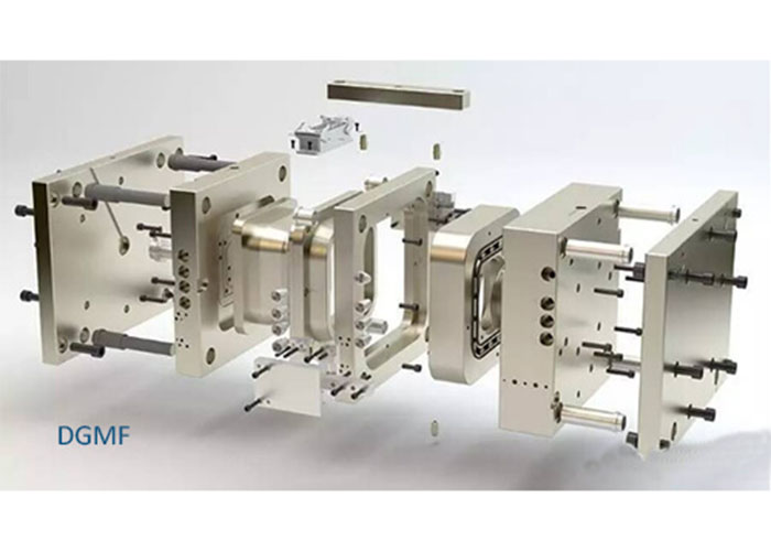
According to the different materials of the mold itself, the mold can be divided into a sand mold, metal mold, vacuum mold, paraffin mold, and so on. Among them, with the rapid development of polymer plastics, plastic injection molds are closely related to people’s lives. Plastic injection molds can generally be divided into injection molding molds, extrusion molding molds, gas-assisted molding molds, and so on.
The most important factors for mold materials are thermal strength and thermal stability. Common mold materials:
Working temperature-molding material-mold material
<300℃ zinc alloy Cr12, Cr12MoV, S-136, SLD, NAK80, GCr15, T8, T10.
300~500℃ aluminum alloy, copper alloy 5CrMnMo, 3Cr2W8, 9CrSi, W18Cr4V, 5CrNiMo, W6Mo5Cr4V2, M2.
500~800℃ Aluminum alloy, copper alloy, steel titanium GH130, GH33, GH37.
800~1000℃ Titanium alloy, steel, stainless steel, nickel alloy K3, K5, K17, K19, GH99, IN100, ЖC-6NX88, MAR-M200, TRW-NASA, WA.
>1000℃ nickel alloy copper-based alloy mold cemented carbide mold.
What are the mold principles?
Here we introduce the working principle of molds.
1. Hot runner system mold principle
2. Inverted hook mechanism in the inclined top
3. Sleeve ejection mechanism
4. Outer hook mechanism of the slider
5. The internal thread automatically unscrews the demoulding mechanism
6. Three-plate mold, needlepoint glue, the sleeve ejection mechanism
7. Sidewall latent glue feeding mechanism
8. Injection mechanism of embedded parts
9. Thimble latent glue feeding mechanism
10. Hub barb mechanism
11. The workflow of the injection molding machine
12. Combination diagram of the snap hook mechanism
13. Explosive mechanism
14. Combined die for the slanting top screw-off mechanism
15. Thread drawing tool drawing
16. Explosive and push plate forming mold drawing
17. Mold drawing of rack dethreading mechanism
18. Motor unthreading die drawing
19. Side thread, motor disengagement diagram
20. Use the opening and closing mold to remove the side thread mechanism mold principle
21. Huff-style thread removal plus push plate mechanism ejection mold principle
22. inclined-top pushing mechanism of complex mold principle
23. Slider core pulling on both sides of the slider mechanism
24. Rotary core-pulling mechanism for die elbow
25. Rotary core-pulling mechanism for die elbow
26. inclined-top slider mechanism pushing-out of complex mold
27. Side Core Pulling Mechanism
28. Rotary core-pulling mechanism for die elbow
If you had any other mold principles. Welcome to inform us.
You may also be interested in the below articles:
Summary Of 50 Injection Mold Structure Operation Dynamic Diagrams