Description
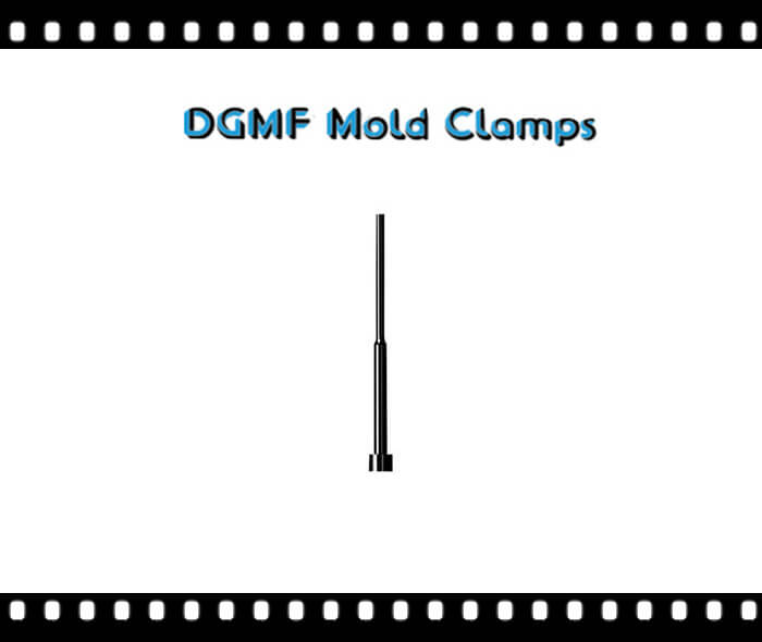
What are Shoulder Ejector Pins?
Nitrided Shoulder Ejector Pins are constructed of premium hot-work die steel. Pinheads are solid forged and annealed. Tight tolerances ensure a friction-free smooth surface.
Nitrided Surface 65-74 HRC
Standard 3″ & 4″ Long Shoulder Pins Are Available
Specials Available Per Your Requirements
Shoulder Ejector Pins drawing
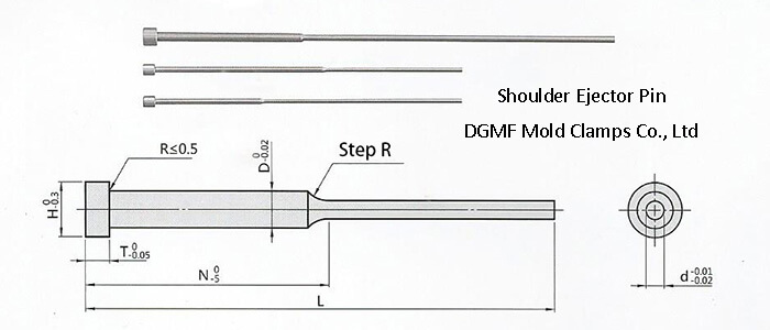
Shoulder Ejector Pins Specifications:
| Model Number | D | H | T | L | d | N | |||||||||
| Standard L(+5) | Specified length L(+0.02) | 40 | 50 | 60 | 70 | 80 | 90 | 100 | 125 | 150 | |||||
| DGMF-007-A (Standard)
DGMF-007-B (Specified length) | 1.5 | 3 | 4 | 100 | 50.00-100.00 | 0.8-1.0 | |||||||||
| 150 | 100.01-150.00 | ||||||||||||||
| 2 | 4 | 100 | 50.00-100.00 | 0.8-1.5 | |||||||||||
| 150 | 100.01-150.00 | ||||||||||||||
| 200 | 150.01-200.00 | ||||||||||||||
| 2.5 | 5 | 100 | 60.00-100.00 | 0.8-2.0 | |||||||||||
| 150 | 100.01-150.00 | ||||||||||||||
| 200 | 150.01-200.00 | ||||||||||||||
| 3 | 6 | 100 | 60.00-100.00 | 0.8-2.5 | |||||||||||
| 150 | 100.01-150.00 | ||||||||||||||
| 200 | 150.01-200.00 | ||||||||||||||
| 4 | 8 | 6 | 150 | 100.00-150.00 | 1.5-3.0 | ||||||||||
| 200 | 150.01-200.00 | ||||||||||||||
| 250 | 200.01-250.00 | ||||||||||||||
| 5 | 9 | 150 | 100.00-150.00 | 2.0-4.0 | |||||||||||
| 200 | 150.01-200.00 | ||||||||||||||
| 250 | 200.01-250.00 | ||||||||||||||
| 6 | 10 | 150 | 100.00-150.00 | 3.0-4.0 | |||||||||||
| 200 | 150.01-200.00 | ||||||||||||||
| 250 | 200.01-250.00 | ||||||||||||||
TO ORDER SPECIFY: Model Number-D-L-d-N-H-T
Shoulder Ejector Pins Product Description
Ejector pins are used to eject completed parts from die molds and are commonly used in the plastics, automotive, Aeromotive, and medical industries, amongst others. The blade shape is used when there is only a small surface area on the finished part.
When the mold is opened, the pins extend into the mold cavity, push the part out, and then retract, allowing the mold to close and be refilled.
Ejector pins usually have the following three kinds:
- Straight ejector pins
- Shoulder ejector pins
- Ejector blades pins
Shoulder Ejector Pins design standards
1. If the thimble is less than 3mm, use two Ejector pins.
2. The top block that is ejected with a rod must be inserted into the top block by 8 mm. The top block must have a guide sleeve, and the guide sleeve must be fixed.
3. If the small top block cannot be fixed with screws, please design with pins for positioning.
4. The R angle of the top piece must be designed.
5. In the case that the mold can use either the top sheet or the ejector pin, the ejector pin is given priority.
6. The Ejector pin has 20-25mm left.
7. The left and right gap of the Ejector pin plate penetrates 0.5 mm.
8. The Ejector pin board must have a lower guide pin and garbage nails.
9. Try to give priority to ejector accessories when resetting the Ejector pinboard. (Except for the spring required by the customer)
10. Try to use a larger Ejector pin (force and life) for ejection.
11. On the premise that the product can be automatically taken off with the inclined top, try to avoid using the gas top.
12. The core and cavity valves should be designed to be concentric (especially transparent products).
13. The mold design carefully calculates the ejection distance to avoid insufficient ejection stroke.
14. For products that do not have the original shape, carefully consider the ejection position and ejection method.
15. Place the oil cylinder on the ejector plate for the mold ejected from the oil cylinder.
16. The valve installation should be disassembled from bottom to top.
17. Try not to fix the core in the push tube with screws, and must be fixed with a pressure plate.
18. The Ejector pin on the inclined surface and the Ejector pin step design is long and bar-shaped to avoid the inconvenience of D-shaped processing.
19. The board under the fixing screw of the inclined top sliding foot is designed to be worn and easy to disassemble.
20. The opposite position of the reset lever should be designed with a cushion insert. (Easy to process and resistant to collision)
21. The ejector hole design of the mold below 300mm is ¢45mm; the design of the mold larger than 300mm is ¢60mm (large mold depends on the situation).
22. There should be more than 5 ejector holes for molds over 400mm.
23. The air cap is a D-shaped air cap on the inclined plane.
24. The 4 corners of the inclined top and the square small straight top block should form an R angle (to reduce friction).
25. The stripper can be designed as a top ring type as far as possible.
DGMF Mold Clamps Co., Ltd supplies the ejector pins, straight ejector pins, ejector sleeve pins, ejector blades, shoulder ejector pins, guide pins, core pins, angle pins, dowel pins, guide bushing, A-type sprue bushing, B-type sprue bushing, C-type sprue bushing, small gate sprue bushing, big gate sprue bushing, etc.
Contact the DGMF team for the injection mold components specification, inventory, pricing.








Reviews
There are no reviews yet.